
- Lister Diesel Parts
- Lister CS Parts
- Lister JP, JK, JS
- Lister CD & CE
- Lister FR
- Lister LD & SL
- HA, HB & HW
- Lister LR Parts
- Lister SR Parts
- Lister ST & STW
- HR, HRW & HL
- Air, Oil & Fuel Filters
- Gaskets & Seals
- Piston, Rod, Rings & Cylinder
- Bearings & Bushes
- Cylinder Head & Fittings
- Fuel System & Governor
- Exhaust, Air Cleaners & Manifolds
- Starter Motor & Crank Handle
- Lubricating Oil System
- Crankcase, Crankshaft & Camshaft
- Cooling System (Air & Water)
- Studs, Nuts & Bolts
- Electrical & Gauges
- Accessories & Other Parts
- HR2G & HR3G Gas Engine Parts
- Lister LT & LV
- Lister TS, TL & TR
- Air, Oil & Fuel Filters
- Gaskets & Seals
- Piston, Rod, Rings & Cylinder
- Bearings & Bushes
- Fuel System & Governor
- Exhaust, Air Cleaners & Manifolds
- Lubricating Oil System
- Cylinder Head & Fittings
- Crankcase, Crankshaft & Camshaft
- Electrical & Gauges
- Starter Motor & Crank Handles
- Studs, Nuts & Bolts
- Cooling System (Air & Water)
- Accessories & Other Parts
- Lister Petter TX
- LPA & LPW
- JA, JAS, JW & JWS
- CR, CD4/6 & CS4/6
- Vintage Lister Parts
- Petter Engine Parts
- Other Engines
- Piston Rings
- Air, Oil & Fuel Filters
- Fuel Injection Parts
- Gaskets & Gasket Sets
- Silencers & Mufflers
- Books & Manuals
- Transfers & Decals
- Starting Handles
- Nuts, Bolts & Studs
- Oilers & Lubricators
- Magneto & Ignition Parts
- Tools & Supplies
- Cylinder Sleeves
- Belts & Pulleys
- Engine Accessories
Lister H to R Fuel & Oil Pump Types & Variations
Note from the Author: If you intend to copy this page in part or its entirety, I kindly ask that you please ask for my permission first, and please do me the courtesy of linking back to this page and giving me credit for the knowledge I have shared. Thankyou…
I know of several significant pump variations that were fitted to the early Lister H to R petrol and paraffin engines, with each type of pump having its own slight variations during their production time, this page shows details of the types I have seen and know of through years of collecting Lister engines as well as from original documents and literature. This article is not intended to be the final say on these pumps, it may contain errors and omissions and is in no doubt missing some vital information and details that I am not aware of yet. If you are reading this page and know of any other variations not detailed here, please kindly let me know, I will do my best keep revising this page as any new information comes to light in the future.
Note: To make things a little less confusing I have done a separate section further down the page for the 1-1/2 to 2HP Lister H engines.
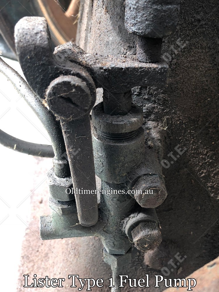
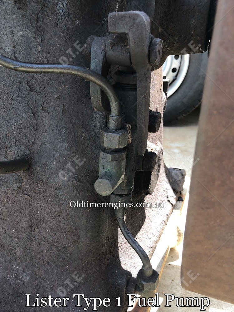
Type 1. The first type of pump that I know of is a single fuel pump only, these pumps are quite rare to see as they were only fitted to the first engines in 1909 and 1910, these engines had the fuel tank cast in the base, and you see them most commonly with the lifting eye on the head. With no oil pump, these engines relied totally on the conrod dipper to distribute the oil for lubrication.
Another significant difference on these early fuel pumps is the priming lever, the lever is attached to the pump body itself, as shown in the photos below, I am not sure if other sizes or variations of this pump were fitted to the larger engines as I have not been able to find any documentation or physical evidence to the contrary.
Photos are taken from a 2.5HP engine No2357 made in 1910.
 |  |
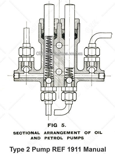
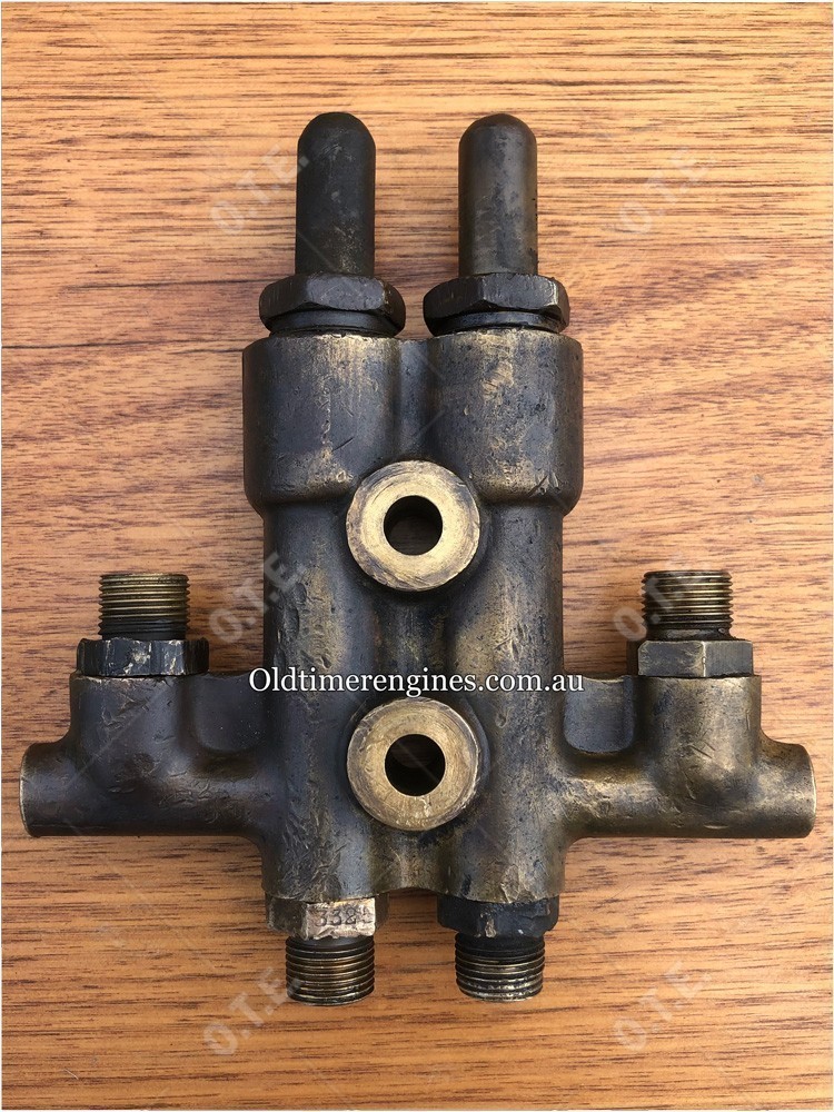
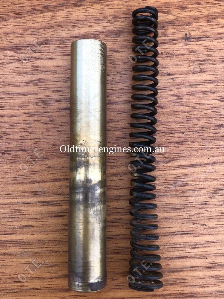
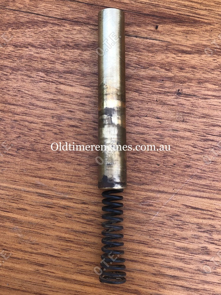
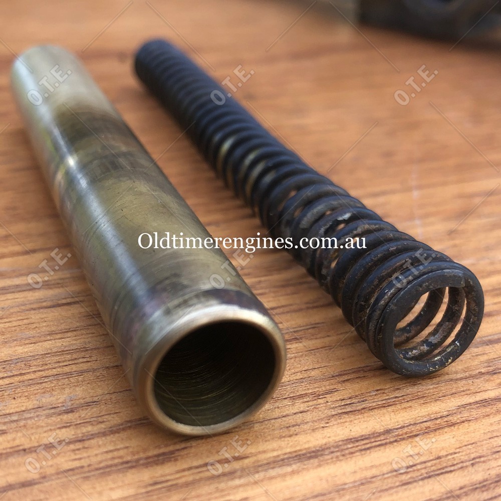
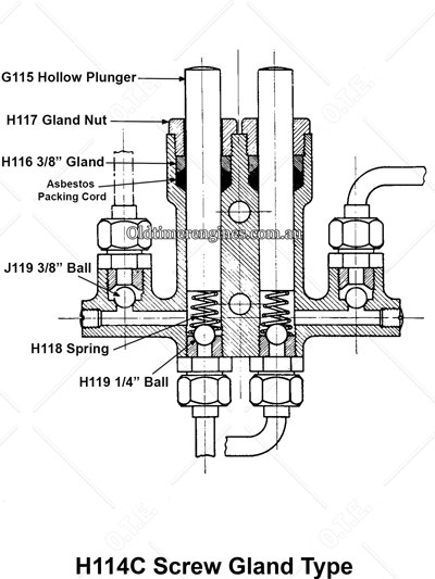
Type 2. The second type is the first of the dual fuel and oil pump design that I know of, the complete assembly could be ordered as a J114C for the 2-1/2HP to 8HP engines. This pump has hollow plungers and a much longer spring than the more common later types, the spring goes up inside the plunger (Refer to images below), as you can see in the images the plunger is hollow for a bit over half its length and the tapered spring goes up inside this cavity. The J115 plunger was also longer than later types, being 3-7/8” long, and the J118 spring was 4-3/4” long.
 |  |
 |  |  |
Both the J107 inlet and J108 outlet unions were 3/8” BSP, with all pipes being 5/16” diameter.
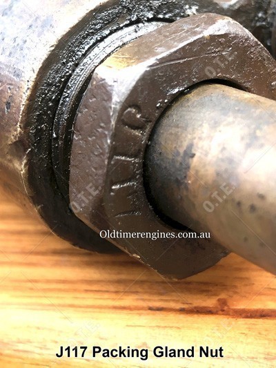
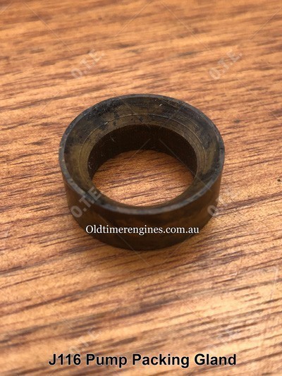
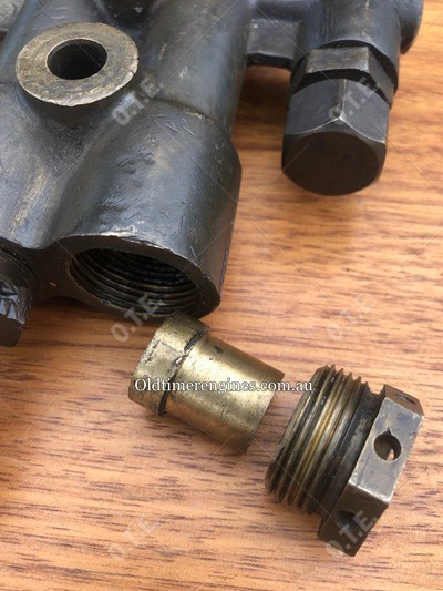
Both the J117 Packing Gland Nuts were 3/4” BSP thread and had plain sided flats, later types had holes in the flats to make adjusting easier behind the flywheel. The J116 Pump Packing Gland had a 5/8” hole (refer to photo bellow), this J116 “Pump Packing Gland” part number is often confused as being the Asbestos Packing Cord, to date I have not been able to find any official reference to a part number for the earlier asbestos packing cord, but in later manuals the Asbestos Cord part number is a 3335.
 |  |
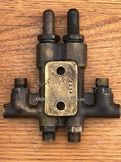
The Type 2 pump body “Screw Gland Type” was a J114 part number for all the single cylinder engine sizes in the J to R range (Excluding the H). The earlier body was heavier than later casings, with a flat mounting face as shown in the picture below.
 |  |
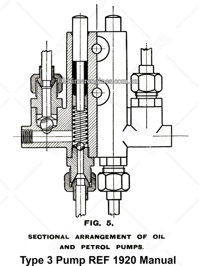
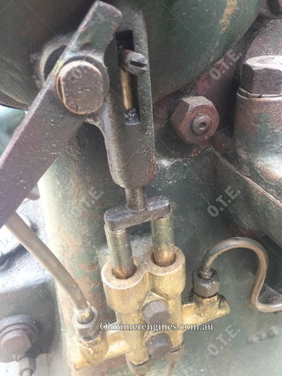
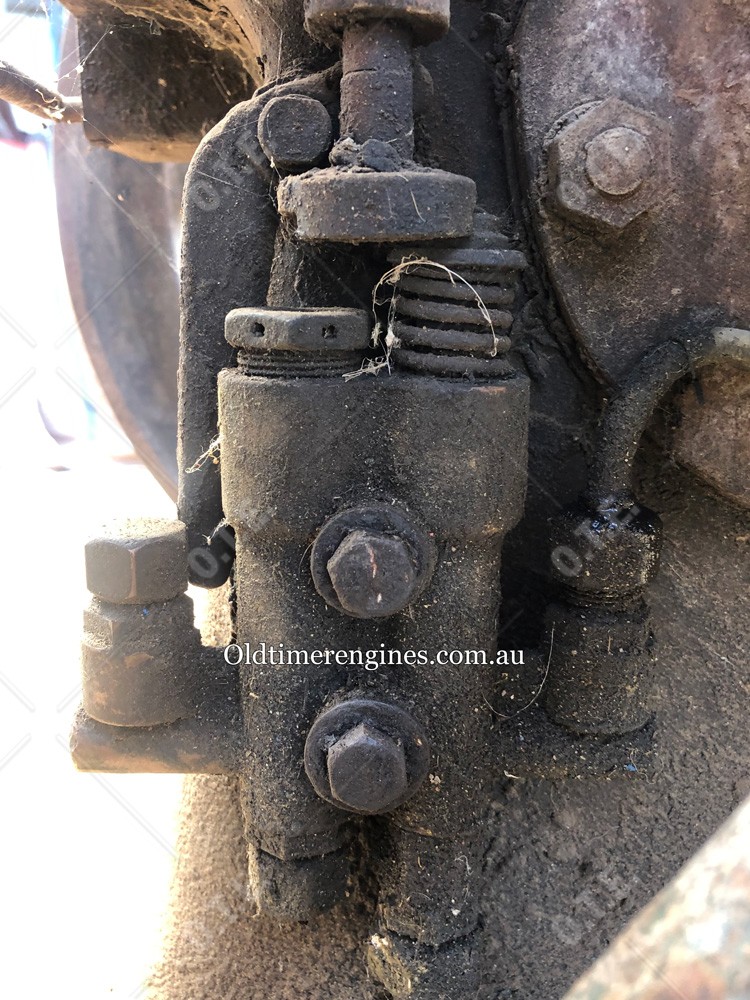
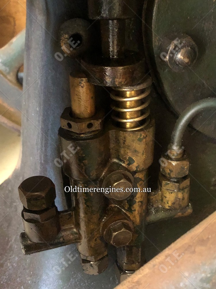
Type 3. These pumps have a very similar look and design to the Type 2 dual fuel and oil pumps, but with one noticeable difference, they had no gland nuts (Refer to drawing and images). The plungers in this pump design where machined down to 5/16” on the bottom end for the J114A pump body, this was to allow for the asbestos packing cord to be wrapped around followed by the “pump packing gland” that the 2-1/4” long J118A spring pushed against.
 | 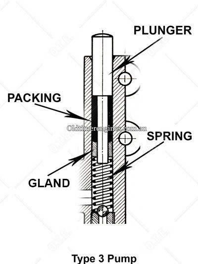 |
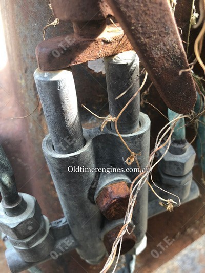
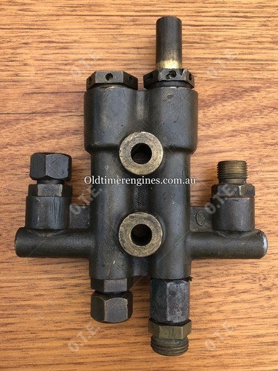
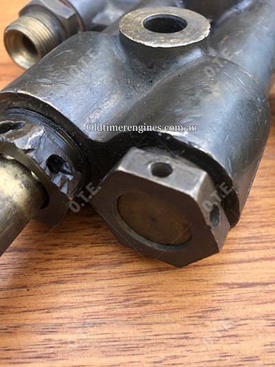
As you can see in the photos below, there were some slight variations in the pump body’s casting in the early part of this design as well, with the first casting still retaining the wider area for the grand nut thread, and flat mounting surface on the back, where the second version had a much more slender top section, and the back mounting surface has been reduced significantly.
 |  |
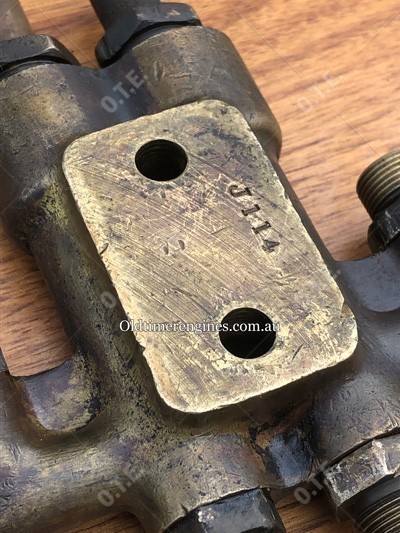
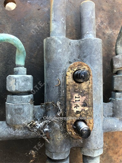
Both examples in these photos show the main body part number being J114A (See Below).
 |  |
Both the J107 inlet and J108 outlet unions where 3/8” BSP, with all pipes being 5/16” diameter.
As far as I can tell, this design was being made in the mid to late teens through to the early 1920’s. I can only assume it was to cut the amount of brass being used during the war years, and possibly cost cutting by reducing the amount of parts?
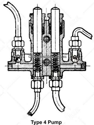
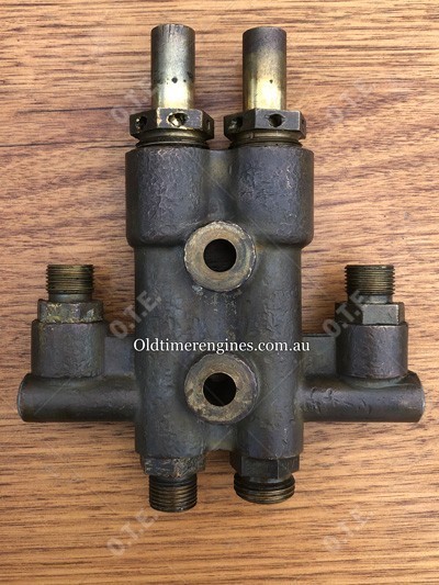
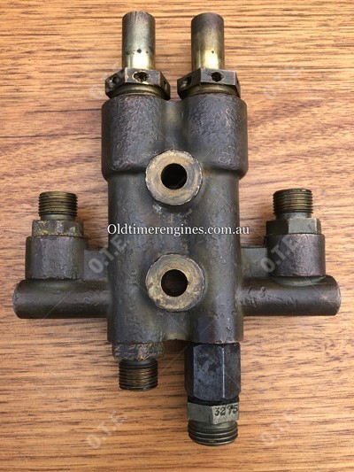
Type 4. One can only assume the Type 3 pump was not that successful in the field, as sometime around the beginning of 1922 the gland nut was reintroduced, which brings us to what I refer to as the type 4 pump. This new pump could be ordered in a complete assembly as a 3321C.
This pump has 3-1/4” long solid plunger in most cases, with a new plunger part number of 3317, this was used with the shorter 2-1/4” long P/N 3324 spring that was first used in the Type 3 pumps as part number J118A (Refer to drawing & images). The gland packing nuts (P/N 3337) also returned in this design with the addition of holes in the flats to make adjusting easier behind the flywheel.
 |  |
The manuals at this point start referring to the older J115B plunger only being used on the N, P, R & Q engines, this plunger is a slightly longer solid type of plunger at 3-5/8” long. All previous pump versions prior to this “Type 4 pump” used the same plunger length (depending on plunger type) for the full J to R engine range.
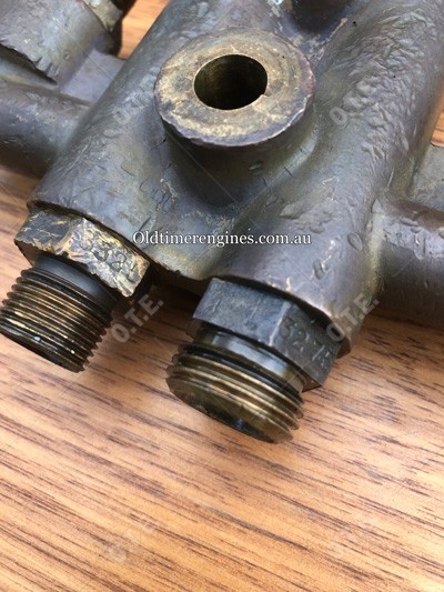
On this pump design the oil suction pipe was increased in size to ½”, with the new ½’ BSP union being P/N 3275. The fuel inlet union retained it’s 3/8 size with the part number being 3325, and both 3/8” outlet connections were P/N 3326.
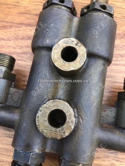
The main pump body’s part number for these pumps is 3321 for all 2-1/2HP to 12HP engines, including the twins.
 |  |
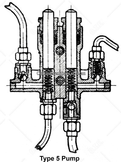
Type 5. This design is what I believe to be the last of these type of fuel/oil pumps Lister made for the petrol and paraffin engines, it retains most of the parts on the “Type 4 pump”, but with a few additions. It is quite difficult to say when some of these changes occurred, but they seem to be from the late 1920’s and into the 1930’s when the additional improvements were added.
A new check valve was added to the oil side of this pump, this was no doubt an improvement added with the launch of the CS 5/1 engines due to the part number being 5-1/B160, with the additional 5-1/B161 Outlet Connection for the lubricating oil, as well as the 8-1/F67 Ball Valve Spring.
 |  |
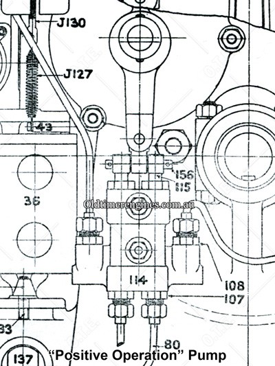
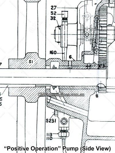
Type 2 & 3 “Positive Operation” Pumps. A rarely seen variation of the fuel/oil pumps that can be found on early H to R and twin cylinder engines made prior to 1922, is the positive operation type pump. On these pumps the plungers are directly driven by a cam with Eccentric Lever pinned to the plungers (See drawings below). The pump bodies and other fittings remained the same except for the plungers, which were made according to each pumps type with the addition of a bored hole at the top for fixing to the eccentric lever (See drawings below).
 |  |
 |  |
Early Twin Cylinder Engines (Pre 1922). According to information in a genuine parts list, twin cylinder engines made prior to 1922 were fitted with a single plunger T32 Screw Gland Type or T32A Plunger Packed Type pump with positive operation plungers. The pump body looks very much like the style used later in the early 1930’s for the CS 5/1 diesels.
Early Paraffin Engines. The early paraffin engines appeared to have their own variations of the Type 2 pump described above according to my research, but I have very little details on these at this stage.
Plunger Variations, Details & Part Numbers.
2-1/2HP to 5HP Engines made prior to 1922:
- J115 Hollow plunger with plain top end, 3-7/8” long. Used with J118 4-3/4 long spring.
- J115B Solid Plunger with plain top end, 3-5/8” long. Used with J118A 2-1/4 long spring.
- J115A Solid Plunger with plain top end and reduced diameter to 5/16” on bottom end. Used with J118A 2-1/4 long spring.
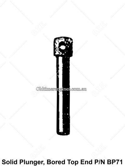
- BP71 Solid Plunger with bored top end. No spring.
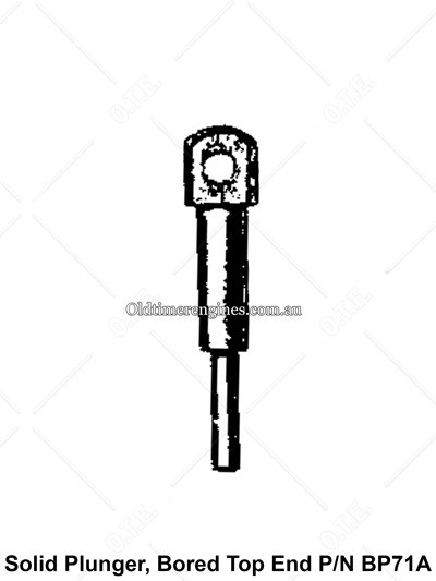
- BP71A Solid Plunger with bored top end and reduced diameter to 5/16” on bottom end. No spring.
2-1/2HP to 5HP Engines made in 1922 and onwards:
- 3317 Solid plunger 3-1/4” long. Used with 3324 2-1/4 Long Spring (Same as J118A spring)
Note: In a later manual (Mid to late 1930’s), the oil side spring was changed to D156, the petrol side retained the 3324 part number.
5-1/2HP to 7-1/2HP Engines made prior to 1922:
- J115 Hollow plunger with plain top end, 3-7/8” long. Used with J118 4-3/4 long spring.
- J115B Solid Plunger with plain top end, 3-5/8” long. Used with J118A 2-1/4 long spring.
- J115A Solid Plunger with plain top end and reduced diameter to 5/16” on bottom end. Used with J118A 2-1/4 long spring.
- BP71 Solid Plunger with bored top end. No spring.
- BP71A Solid Plunger with bored top end and reduced diameter to 5/16” on bottom end. No spring.
6HP to 9HP Engines made in 1922 and onwards:
- J115 Hollow plunger with plain top end, 3-7/8” long. Used with J118 4-3/4 long spring
- J115B Solid Plunger with plain top end, 3-5/8” long. Used with J118A 2-1/4 long spring
- J115A Solid Plunger with plain top end and reduced diameter to 5/16” on bottom end. Used with J118A 2-1/4 long spring
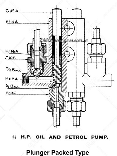
H Type 1-1/2HP to 2HP Pumps. The lister H had its own unique versions of the Type 2, Type 3 and Type 4 dual fuel and oil pumps I have detailed previously. This pump was a scaled-down version of the larger ones found on the J to R engines, and almost all parts are unique to this smaller pump.
1-1/2HP to 2HP Pump Body
There are 2 pump body variations recorded for the H that I am aware of, being the H114 Screw Gland Type and the H114A Plunger Packed Type.
 |  |
Plunger Variations 1-1/2HP to 2HP Pump
Several plungers and spring variations can be found in various manuals, some of which are noted here.
- G115 3/8” diameter hollow plunger with plain end, 2-3/4” long. Used with H118 2-1/2 long spring.
- H115 3/8” diameter solid plunger with bored top end, 3-5/16 long. No spring.
- H115B 3/8” diameter solid plunger with plain end, 2-5/16 long. Used with H118B 1-5/8” long spring.
- G115A 15/32 diameter solid plunger with plain end and reduced diameter to 1/4” on bottom end, total length 2-7/8” long. Used with H118A 2-1/4” long spring.
- H115A 15/32 diameter solid plunger with bored top end and reduced diameter to 1/4” on bottom end, total length 3-3/8” long. No spring.
Twin Cylinder Petrol & Paraffin Engines. Much like the pumps later used on the first CS diesels (details further down this page), the later twin cylinder petrol and paraffin engines used the dual fuel and oil pump design with the oil pump side capped off.
The First Lister CS Diesels. Another variation of the dual fuel and oil pump design was used on the very early CS 5/1 diesels, the first of these engines were fitted with the J to R range dual fuel and oil pumps despite only needing the oil side of the pump, the fuel side was capped off as can be seen in the photos below. There were also a few variations in these pumps as the design was tweaked, a few I know of are the gland nut eventually being removed and spring being upgraded to a much heavier external type, a circlip groove was also added to plunger to retain a washer on top of this new heavier spring. At some stage before around engine number 10,000, the pumps on the CS were redesigned to the dedicated single plunger oil pump design we all know of on the CS.
 |  |
 |  |
 |
This article has been written by Rob Johnson, Brisbane Australia, vintage stationary engine collector, restorer and owner of Old Timer Engines.